Tag Archives: instruction

Statistical Orbit Determination

If you wish to receive class updates and announcements please submit your email here!

[contact-form][contact-field label=”Email” type=”email” required=”1″ /][/contact-form]

Class time/Preliminary Notes

I will be teaching a statistical orbit determination course this summer. This will be on my own time. All lectures will be posted to YouTube. I will be teaching the course out of Bob Schutz’s, Byron Tapley’s, and George H. Born’s, Statistical Orbit Determination. Feel free to use any textbook you desire but the problems and solutions will be assigned from this text. I have included some precursor notes in question and answer format on statistics and probability below.

AppendixA-ProbabilityAndStatistics

Syllabus

AEM_StatisticalOrbitDetermination_Syllabus_CRS

STATISTICAL ORBIT DETERMINATION

EXECUTIVE SUMMARY:

Orbit Determination (OD) is the problem of determining the best estimate of the state of a spacecraft whose initial state is unknown, from observations influenced by random and systematic errors, using a mathematical model that is not exact. Mordern OD is used to support all space missions from JSpOC’s observations of artificial Earth satellites to the International Space Station’s trajectory planning incorporating elements of probability, statistics, and matrix theory. A special projects class is needed to cover this vital part of the space curriculum that arguably makes the backbone of any space program.

DISCUSSION:

Modern OD approaches have been developed by the NASA Jet Propulsion Laboratory (JPL) to fulfill Earth and planetary navigation requirements and at the NASA Goddard Space Flight Center (GSFC) and the Department of Defense Naval Surface Weapons Center in applications of satellite tracking to problems in geodesy, geodynamics, and oceanography. The Joint Space Operations Center (JSpOC) at Vandenberg Air Force Base, the Conjunction Assessment Risk Analysis (CARA) at GSFC, and Trajectory Operation Officers (TOPO) at Johnson Space Center (JSC) use modern OD techniques in applications of satellite tracking, conjunction assessment, and protecting vital assets from the International Space Station to the National Reconnaissance Office (NRO) spy satellites.

Clearly, OD is an important part of any space mission. The proposed class will use the classical text, Statistical Orbit Determination, by Drs. Byron Tapley, Bob Schutz, and George Born. This basic OD course will cover:

  • Introduction to OD problem
    • Dynamic system and associated state
    • Observations are non-linear functions of state variables
    • Classical well-determined approach
    • Modern over-determined approach
  • Observations to measure satellite motion
    • Ground-based systems: laser, radiometric, etc.
    • Space-based systems: GPS, etc.
    • Error sources and media corrections
  • Non-linear OD reduced to linear state estimation
    • Application of linear system theory
    • Incorporation of algorithms to computational environment
    • Sequential processing of observations
    • Control of real-time processes

This will be supported by background and supplemental information in:

  • Probability and Statistics
  • Review of Matrix Concepts
  • Examples of State Noise and Dynamic Model Compensation
  • Solution of the Linearized Equations of Motion

Students can expect to incorporate their classroom knowledge into real-life by building optical and radiometric sensors supporting The University of Alabama’s new satellite ground station.

LECTURES:

Lecture 1 – Orbit Determination Concepts

Lecture 2 – Orbital Mechanics Review

FreeFlyer Demonstration: 2:00pm Sep. 28, 2017 for UA faculty and students

I will be giving a demonstration of FreeFlyer on Thursday, September 28 at 2:00 pm in SERC 3070. Faculty and Students feel free to drop on by! I have attached the flyer, here: FreeFlyerWithAttitude

Christopher Simpson will present a FreeFlyer demonstration, “FreeFlyer with Attitude,” on Thursday, September 28, 2017 at 2:00 pm in SERC 3070. FreeFlyer with Attitude will showcase the high-fidelity flight dynamics software with a Earth imaging satellite mission plan with specific pointing requirements. FreeFlyer is currently used on several NASA missions, including the Magnetosphere Multiscale (MMS) mission which set the record for closest flying formation at 7.2 km in September of 2016. Mr. Simpson recently interned with a.i. solutions, Inc. over the summer and worked with the FreeFlyer Tech Support team. He recently graduated with his B.S. in Aerospace Engineering and Mechanics from The University of Alabama in May 2016. He was recently awarded a SMART scholarship from the Naval Air Warfare Center – Weapons Division, China Lake. He is pursuing his Ph.D. at The University of Alabama under Dr. Charles O’Neill.

DemonstrationPhotos

WHAT WHO WHERE WHEN
Showcase of FreeFlyer Students & Faculty SERC 3070 2:00 PM

September 28, 2017

 A high fidelity flight dynamics software comparable to STK used on multiple NASA missions, including the ISS, MMS, OSIRIS-Rex, and for the SLS All with an interest in spacecraft and astrodynamics are welcome


2017 ESPRMC Graduate Research Symposium – The University of Alabama

I will be presenting “Benefits of Tracking Aids on a 1U CubeSat,” on Thursday, April 13 at the 2017 ESPRMC Graduate Research Symposium. Dr. O’Neill was my co-author. I hope to see you there.

Abstract:

Incoporating active/passive tracking aids into the design of a university/high school CubeSat mission promotes good space stewardship. Tracking aids are necessary for improved tracking covariance of CubeSats. Tracking aid support and design-space cost are covered. Reflectarrays, patch array(s), and deployable antennas show the potential benefit of transmitting data over S-band frequencies and tracking aids that enhance the mission capabilities. Passive and active tracking aids with low impact on the mission provide reduced covariance of CubeSats orbit tracks shown through use of modeling tools.

Cesium Demo Using STK Scenario/TLE Data

Coming Soon: Orbital Mechanics/Astrodynamic Problem Solutions

While in the midst of preparing for a journal paper I decided that I wanted to showcase my abilities. I will solve all the problems from Vladimir Chobotov’s Orbital Mechanics, Third Edition, and Richard Battin’s An Introduction to the Mathematics and Methods of Astrodynamics, Revised Edition and post the solutions online. I hope to have this done by January 2.

Not only will this be a good review for myself but it will showcase my abilities to solve problems relating to the field I want to enter. Hopefully, it will prove to be a valuable tool in the future.

As for the featured picture: I am in the process of getting myself certified Level 1 with STK. I dropped this scenario into Cesium while I was practicing and exploring STK before the exam. My exam is due December 22. I will let you know the results soon!

Gulfstream G-V CAD Update (Or: "Who Wants to be a CAD Monkey?")

To see previous post click here. This time I will cover how I created all the parts of the G-V.

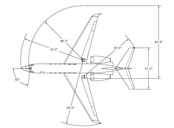
It pays to read all the way through. Last week, I thought that I had found technical drawings showing all the dimensions of the G-V. What I had actually found was a drawing describing taxi clearance.

GV_Top_TaxiClearance

Drawing courtesy of NSF/NCAR and Lockheed Martin

So… back to the drawing board. Excuse the pun.

I divided the G-V into 4 parts: wing, fuselage, empennage, and engine. The more I separate the easier it makes it on me to get the details right.

Wing:

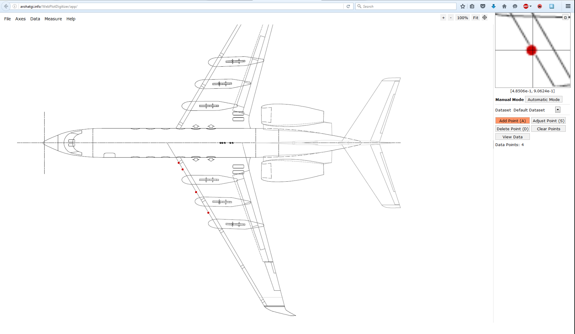
Going back to our Investigator Handbook from the NSF/NCAR we use a different technical drawing. In 5.1.5 of the handbook the pylon mounts along the wing for scientific investigation are shown. Using WebPlotDigitizer we create a series of points approximating the top of the wing. You have the option to save the points as a .CSV. Since I use Autodesk Inventor I can import Excel files with a series of data points. There are similar features with SolidWorks but I’m more comfortable with Inventor.

GV_Plotting_Points.png

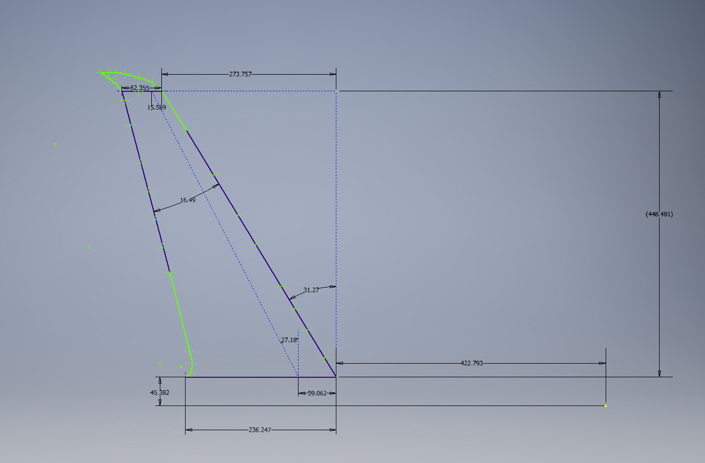
Once in Inventor I can begin making the wing. It’s almost connect-the-dots: except you need to check dimensions. You won’t have gotten all your points in the plot digitizer just right either so you should focus on getting the majority of the points as opposed to every single one. With more experience you’ll find that the more points you have on a curved surface the closer you can approximate the curve. The c4 angle is 27° which is verified through the use of construction lines.

GV_Inventor_Drawing_Through Points.PNG

2D Sketch in Inventor of G-V planform wing area

Now we have a sketch how do we create our 3D model?

Using the excellent resource The Incomplete Guide to Airfoil Usage we can determine the airfoils used for the root and tip of the wing. This provides us with the G-IV root airfoil, NACA 0012 modified, and the tip airfoil, NACA 64A008.5 modified.We don’t need to worry about the modifications or that it is G-IV because we’re developing a base model for concept development. The G-IV airfoils are essentially the same as the G-V anyways. If you were trying to get the airflow characteristics of a G-500 to the 99th percentile then you are either working for Gulfstream and can pull the model yourself or you should contact Gulfstream.

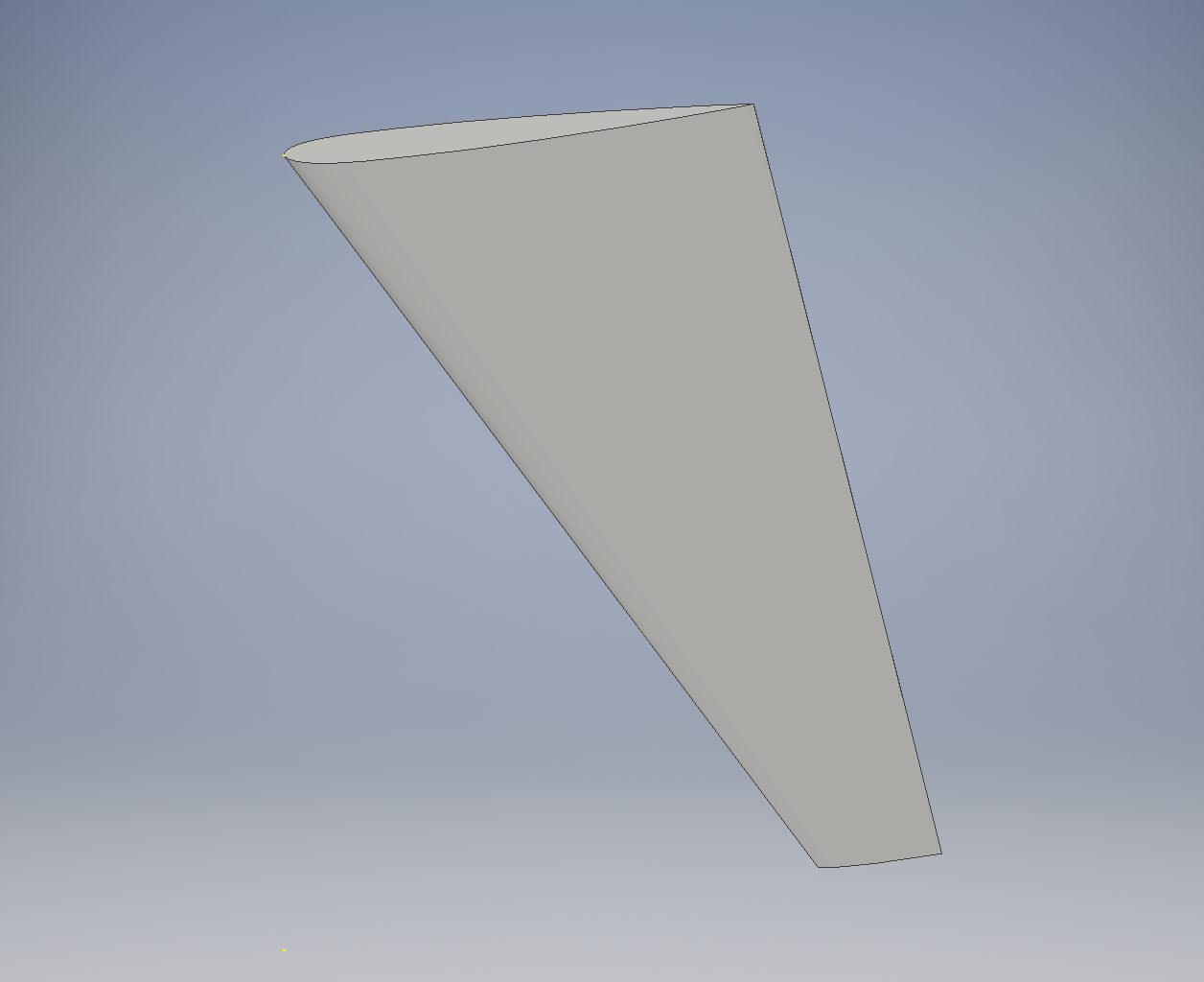
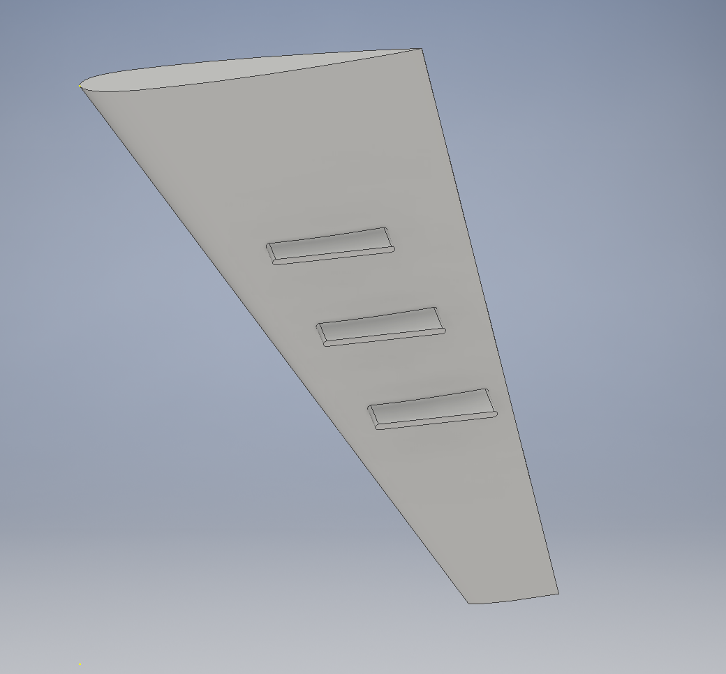
Using the 2D sketch we just created we can place the airfoils at their respective locations and loft the wing between them. That should give you something like this:

GV_Isometric_Wing Loft.PNG

Lofted Wing

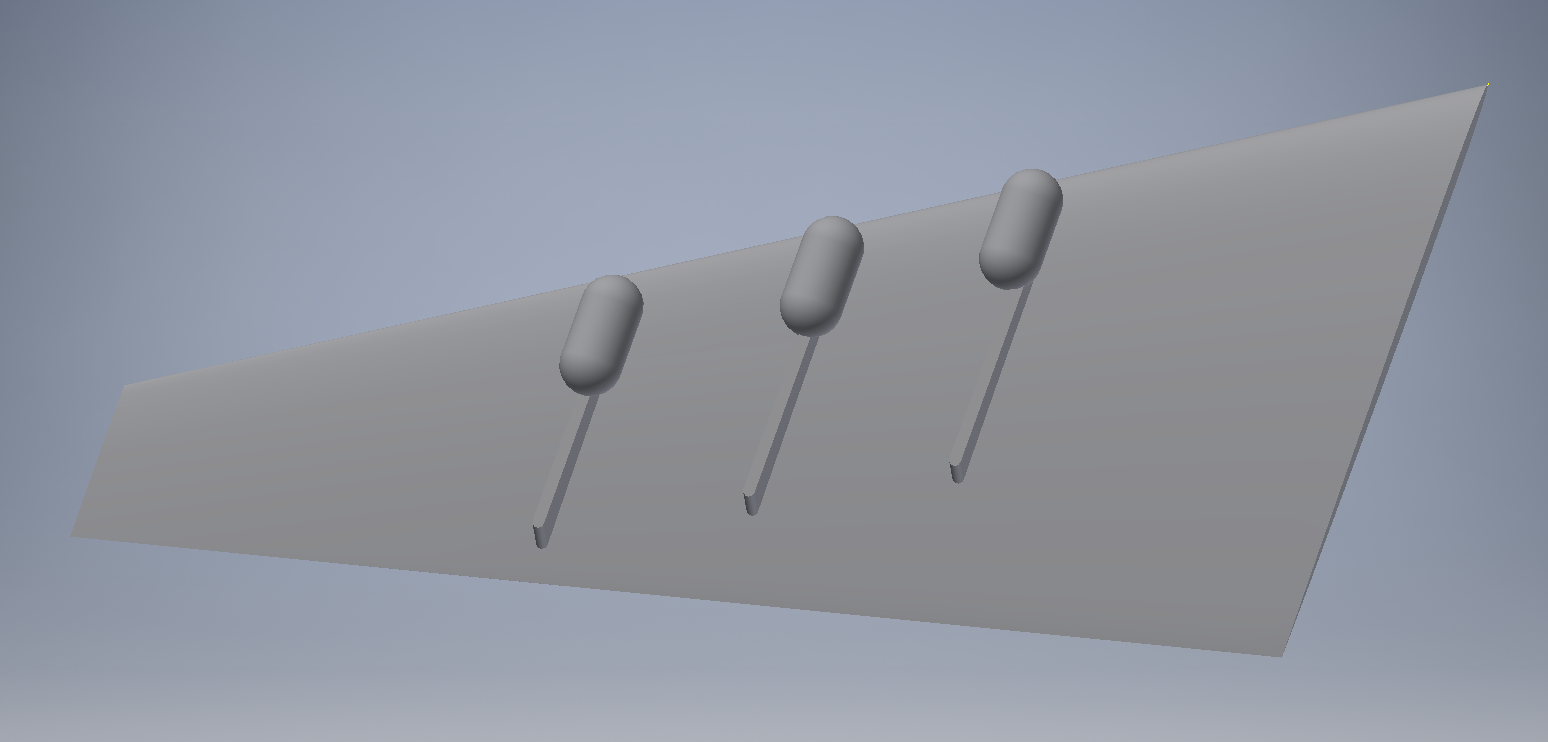
Then, using the sketch, which I hid in the previous image, create a work plane and extend your pylons in the appropriate locations.

GV_Isometric_Wing_Pylon.PNG

Extend your pylons through the wing

I have a concept structure that I’m developing below. Currently, Dr. O’Neill is trying to provide Dr. Yan with some feedback on design of radio antenna integration for a Gulfstream G-V and I’m creating the CAD concept models. I cannot picture these currently because it’s ongoing research. Instead here are some example tank concepts.

GV_Example_Concepts

Example Concept

Fuselage:

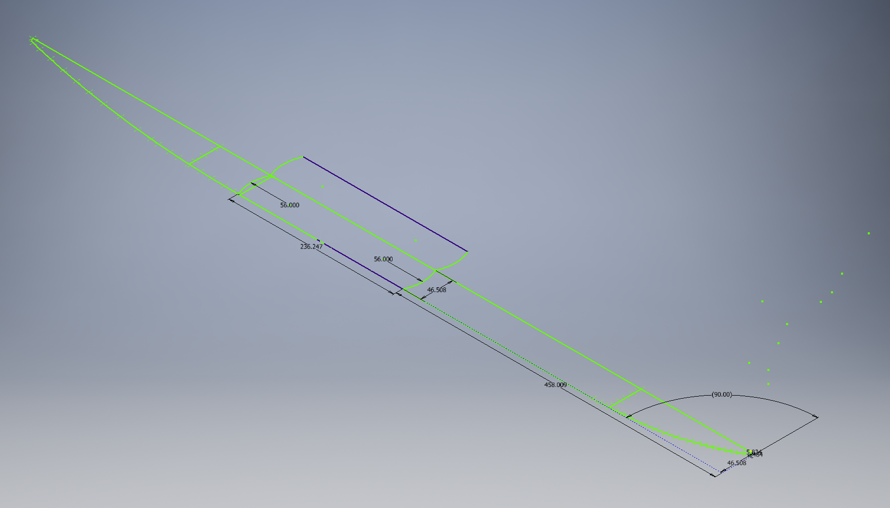
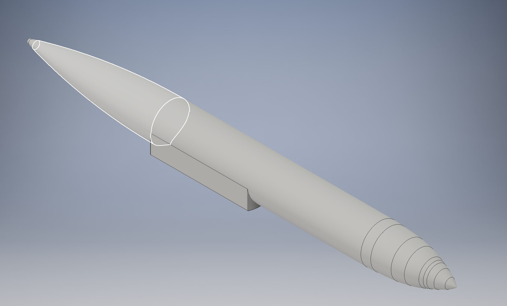
The fuselage is created in a similar process to the wing. We plot a series of points and rotate the fuselage around the centerline. We will create the saddle with straight sides and extend it through the fuselage. The trick here is that I created 2 different sketches on the same plane to avoid weird things that happen if I make the pieces sequentially.

GV_Isometric_Fuselage.PNG

Sketches for the Saddle and Fuselage Body

GV_Fuselage_Complete.PNG

Fuselage Rotated and Extended

Rolls-Royce BR710A1-10 Turbofan Engine:

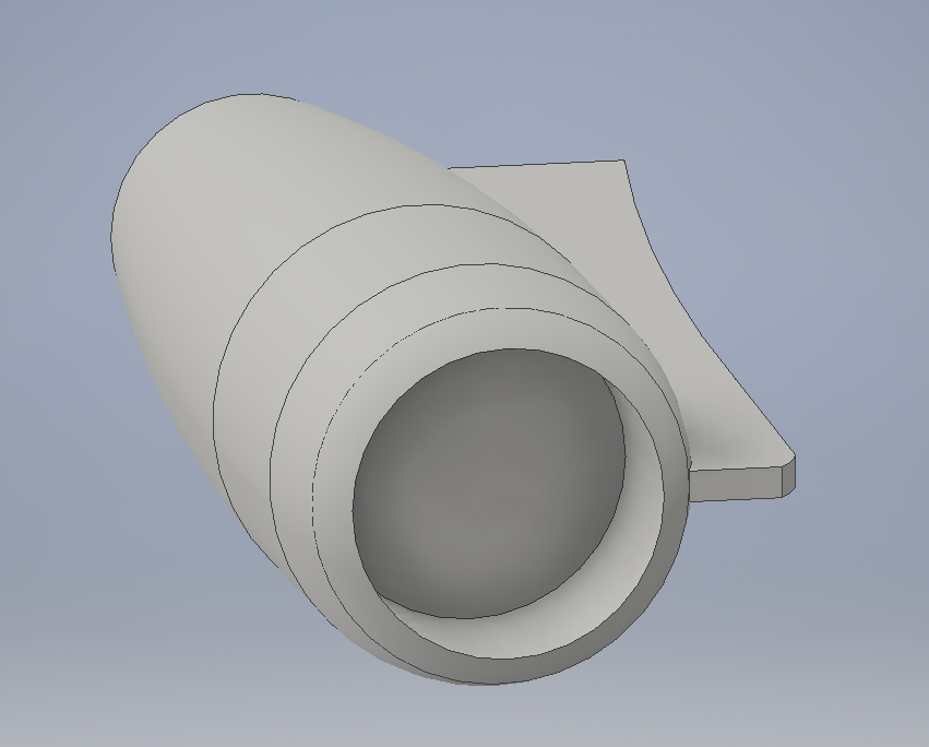
The Rolls-Royce engine is built in the exact same way as the fuselage. Two sketches on top of each other and then a rotation and an extension. I then cut into the engine to make it look like an actual engine but if you know how to extend by know this should be an easy process.

GV_Engine.PNG

Engine Section

Empennage:

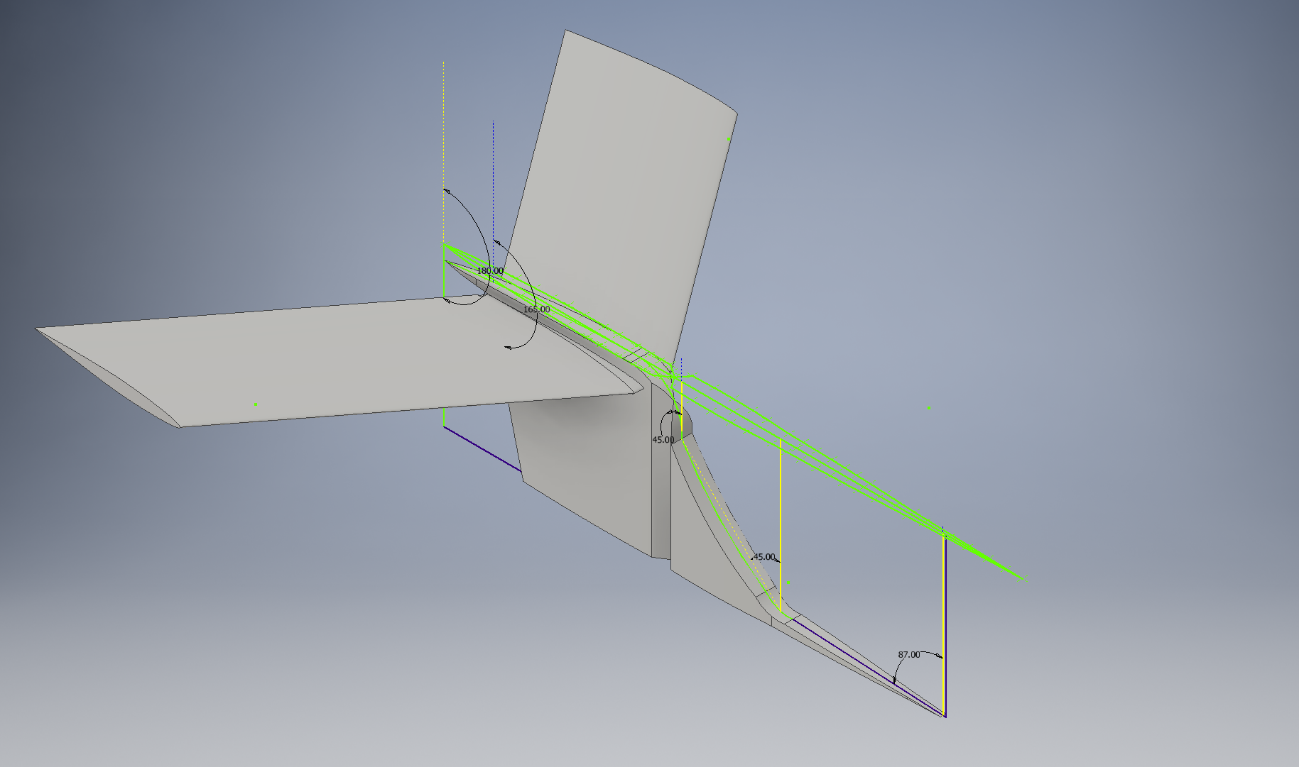
The tail is created by taking the points from the top view. The points are extended and then cut from the side view. The wings are lofted from the vertical stabilizer using the NACA 64A008.5 airfoil for the root and tip.

GV_Empennage.PNG

Empennage Section

Complete Gulfstream G-V:

The current configuration of the Gulfstream is shown below. The illustrations shown are from the presentation I created for Dr. Yan. The antenna configuration is removed. Inventor has some nice illustration tools that are exceptionally useful when presenting.


The slideshow shows the stages of development of the Gulfstream G-V. The first model is all one piece. The second model is a lofted fuselage that experienced connectivity issues. The third is the most promising and will probably stay until I need to create updates for higher fidelity. The higher fidelity will be required when we run the antenna configuration through CFD to test the drag force produced by the array. As you can see I abandoned the wingtips until I have the antenna array configuration fixed.

Gulfstream G-V CAD Update (Or: “Who Wants to be a CAD Monkey?”)

To see previous post click here. This time I will cover how I created all the parts of the G-V.

It pays to read all the way through. Last week, I thought that I had found technical drawings showing all the dimensions of the G-V. What I had actually found was a drawing describing taxi clearance.

GV_Top_TaxiClearance

Drawing courtesy of NSF/NCAR and Lockheed Martin

So… back to the drawing board. Excuse the pun.

I divided the G-V into 4 parts: wing, fuselage, empennage, and engine. The more I separate the easier it makes it on me to get the details right.

Wing:

Going back to our Investigator Handbook from the NSF/NCAR we use a different technical drawing. In 5.1.5 of the handbook the pylon mounts along the wing for scientific investigation are shown. Using WebPlotDigitizer we create a series of points approximating the top of the wing. You have the option to save the points as a .CSV. Since I use Autodesk Inventor I can import Excel files with a series of data points. There are similar features with SolidWorks but I’m more comfortable with Inventor.

GV_Plotting_Points.png

Once in Inventor I can begin making the wing. It’s almost connect-the-dots: except you need to check dimensions. You won’t have gotten all your points in the plot digitizer just right either so you should focus on getting the majority of the points as opposed to every single one. With more experience you’ll find that the more points you have on a curved surface the closer you can approximate the curve. The c4 angle is 27° which is verified through the use of construction lines.

GV_Inventor_Drawing_Through Points.PNG

2D Sketch in Inventor of G-V planform wing area

Now we have a sketch how do we create our 3D model?

Using the excellent resource The Incomplete Guide to Airfoil Usage we can determine the airfoils used for the root and tip of the wing. This provides us with the G-IV root airfoil, NACA 0012 modified, and the tip airfoil, NACA 64A008.5 modified.We don’t need to worry about the modifications or that it is G-IV because we’re developing a base model for concept development. The G-IV airfoils are essentially the same as the G-V anyways. If you were trying to get the airflow characteristics of a G-500 to the 99th percentile then you are either working for Gulfstream and can pull the model yourself or you should contact Gulfstream.

Using the 2D sketch we just created we can place the airfoils at their respective locations and loft the wing between them. That should give you something like this:

GV_Isometric_Wing Loft.PNG

Lofted Wing

Then, using the sketch, which I hid in the previous image, create a work plane and extend your pylons in the appropriate locations.

GV_Isometric_Wing_Pylon.PNG

Extend your pylons through the wing

I have a concept structure that I’m developing below. Currently, Dr. O’Neill is trying to provide Dr. Yan with some feedback on design of radio antenna integration for a Gulfstream G-V and I’m creating the CAD concept models. I cannot picture these currently because it’s ongoing research. Instead here are some example tank concepts.

GV_Example_Concepts

Example Concept

Fuselage:

The fuselage is created in a similar process to the wing. We plot a series of points and rotate the fuselage around the centerline. We will create the saddle with straight sides and extend it through the fuselage. The trick here is that I created 2 different sketches on the same plane to avoid weird things that happen if I make the pieces sequentially.

GV_Isometric_Fuselage.PNG

Sketches for the Saddle and Fuselage Body

GV_Fuselage_Complete.PNG

Fuselage Rotated and Extended

Rolls-Royce BR710A1-10 Turbofan Engine:

The Rolls-Royce engine is built in the exact same way as the fuselage. Two sketches on top of each other and then a rotation and an extension. I then cut into the engine to make it look like an actual engine but if you know how to extend by know this should be an easy process.

GV_Engine.PNG

Engine Section

Empennage:

The tail is created by taking the points from the top view. The points are extended and then cut from the side view. The wings are lofted from the vertical stabilizer using the NACA 64A008.5 airfoil for the root and tip.

GV_Empennage.PNG

Empennage Section

Complete Gulfstream G-V:

The current configuration of the Gulfstream is shown below. The illustrations shown are from the presentation I created for Dr. Yan. The antenna configuration is removed. Inventor has some nice illustration tools that are exceptionally useful when presenting.


The slideshow shows the stages of development of the Gulfstream G-V. The first model is all one piece. The second model is a lofted fuselage that experienced connectivity issues. The third is the most promising and will probably stay until I need to create updates for higher fidelity. The higher fidelity will be required when we run the antenna configuration through CFD to test the drag force produced by the array. As you can see I abandoned the wingtips until I have the antenna array configuration fixed.